
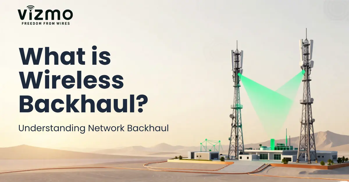
Wireless Backhaul Network: How Network Backhaul Works
A wireless access point can give a device a strong local connection, but that traffic still needs a path to the wider network. The part of the network that carries traffic from access sites towards the core network, control centre, data centre or cloud is known as network backhaul.
A wireless backhaul network performs this job using radio links instead of relying only on fibre or Ethernet cabling. It can connect buildings, remote sites, industrial facilities, communication towers, field equipment and other network locations where installing cable is difficult, slow or expensive.
In a typical backhaul communication network, traffic moves from devices through the access and aggregation layers, crosses a wired or wireless backhaul link, and then reaches the transport or core network.
Wireless backhaul is widely used in mining, oil and gas, manufacturing, utilities, transportation, public safety, private wireless networks and remote monitoring systems. Its performance depends on network architecture, operating frequency, link budget, antenna design, capacity, interference and site conditions.
This guide explains the network backhaul meaning, how wireless backhaul works, common backhaul technologies, equipment, architecture, performance requirements and the steps involved in designing a reliable backhaul network.
For a wider view of how access, transport and core systems fit together, see our guide to industrial wireless network architecture.
What Is Network Backhaul?
Network backhaul is the part of a communication network that transports combined traffic from access networks, gateways, base stations or remote sites towards central network infrastructure.
In simple terms, the network backhaul meaning is the connection between the local access layer and the network that processes, routes or stores the traffic.
For example, an IP camera may first connect to a wireless access point. Several cameras, sensors or controllers may use the same local network. Their traffic is collected and then carried through a backhaul link towards a control room, data centre, private network or cloud platform.
Typical Network Backhaul Data Path
- Devices, sensors, cameras and controllers connect to the access network.
- An access point, gateway, switch or base station collects the traffic.
- The aggregation layer combines traffic from multiple devices or access points.
- The backhaul link carries the combined traffic towards the wider network.
- The transport or core network routes the traffic to the required destination.
- The traffic reaches a data centre, cloud platform, control centre or another network service.
The backhaul layer carries traffic from many devices, so it can become a network bottleneck if it is not sized correctly. Low capacity, high latency, interference or an unstable link can affect the whole communication system even when the local access network is working well.
This is why backhaul design is an important part of industrial wireless infrastructure.
What Does Backhaul Mean in Networking?
In networking, backhaul describes the connection that moves traffic away from the access layer and towards the wider transport or core network.
The exact technology can vary. A backhaul connection may use fibre, Ethernet, microwave, Wi-Fi-based radio links, cellular networks, satellite communication or a combination of technologies.
Backhaul vs Backbone Network
Backhaul and backbone are related, but they are not always the same part of the network.
The backhaul network usually connects access or aggregation sites to a higher-level transport network. The backbone network provides high-capacity transport between major network locations, data centres, core sites or regions.
In a large system, traffic may move from access to backhaul and then from backhaul into the backbone or core network.
What Is Wireless Backhaul?
Wireless backhaul carries network traffic between locations using radio communication instead of continuous physical cabling.
A typical wireless backhaul system uses radios and antennas at two or more fixed locations. The radios send IP or Ethernet traffic over an RF link between the sites.
A wireless backhaul link may connect:
- Industrial buildings
- Remote mine sites and control centres
- Communication towers
- Utility substations
- Oil and gas field locations
- Roadside or railway infrastructure
- Private LTE or 5G sites
- Remote cameras and monitoring systems
Wireless backhaul links may cover a short distance between nearby buildings or several kilometres between remote sites. Actual range and throughput depend on frequency, transmit power, antenna gain, channel width, receiver performance, terrain, interference and available fade margin.
One common design is point-to-point wireless backhaul, where two fixed sites communicate directly through directional antennas.
Before selecting equipment, engineers should calculate whether the radio path has enough signal margin. Our guide to RF link budget calculation for outdoor wireless links explains the main factors involved.
How Does a Wireless Backhaul Network Work?
A wireless backhaul network takes traffic from a local network, converts that traffic into radio signals, sends it across an RF path and delivers it to another network location.
The process can be understood in four main stages.
1. Devices Connect to the Access Network
Sensors, PLCs, cameras, machines, user devices and industrial controllers first connect to a local access point, gateway, switch or base station.
This is the access layer. Its main role is to connect end devices to the local network.
2. Traffic Is Aggregated
Traffic from several devices or access points is combined at a switch, router, gateway or aggregation site.
The backhaul link therefore needs to handle the combined traffic from the devices that depend on it, not just the demand from one endpoint.
3. The Backhaul Radio Sends the Traffic
A backhaul radio takes Ethernet or IP traffic and sends it across the selected RF channel.
For a point-to-point link, directional antennas are normally aimed towards each other. This helps focus RF energy on the required path and limits unwanted signals from other directions.
4. Traffic Enters the Transport or Core Network
The radio at the far end receives the RF signal and forwards the network traffic to a router, switch, control centre, data centre, cloud connection or core network.
Typical Wireless Backhaul Data Flow
Devices
PLCs, sensors, cameras
Access Network
AP, gateway or switch
Aggregation
Combined traffic
Radio A
Wireless Backhaul Link
Radio B
Core Network
Cloud or control centre
Before deployment, the Vizmonet RF Link Planner can help evaluate terrain, antenna height, path clearance and possible obstructions along a wireless link.
Backhaul Network Architecture
Backhaul network architecture describes how access sites, aggregation points, backhaul links and the core network are connected.
A clear architecture helps engineers understand where traffic is collected, where capacity is required and where redundancy should be added.
Access Network
The access network connects end devices such as cameras, sensors, machines, user terminals and industrial equipment.
Depending on the system, the access layer may use Wi-Fi, Ethernet, cellular, industrial wireless protocols or other communication technologies.
Aggregation Layer
The aggregation layer combines traffic from several access points, gateways or local networks.
This is an important design point because the backhaul connection must provide enough capacity for the total traffic that reaches the aggregation site.
Backhaul Layer
The backhaul layer carries this combined traffic towards the wider network.
It may use a single point-to-point radio link, several wireless hops, fibre, Ethernet or a hybrid design.
Transport and Core Network
After crossing the backhaul link, traffic can enter a transport network, core router, data centre, cloud gateway or control system.
The core network then handles routing, central services, security policies, applications and connections to other networks.
Redundant Backhaul Architecture
Critical networks should not depend on one communication path where a single failure could stop the service.
Redundancy can include:
- Two separate wireless links
- Different frequency bands
- Different physical routes
- Wireless backup for fibre
- Fibre backup for wireless
- Automatic routing or failover
The right choice depends on the required network availability, site layout and business impact of a link failure.
Backhaul Network Technologies
There is no single backhaul network technology that is best for every deployment. Engineers select the transport method based on distance, capacity, latency, site access, available spectrum, environment, installation time and budget.
| Technology | Typical Use | Main Design Factors |
|---|---|---|
| Fibre Backhaul | Permanent high-capacity infrastructure | Route, civil work, cost and installation time |
| Point-to-Point Wireless | Fixed links between two sites | LOS, Fresnel zone, link budget and interference |
| Microwave Backhaul | Medium- and long-range fixed links | Frequency, path length, antenna gain and fade margin |
| mmWave / E-Band | High-capacity shorter links | Rain, path blockage and link distance |
| Wi-Fi / Fixed Wireless Backhaul | Private, industrial and enterprise networks | Spectrum, channel planning and capacity |
| 4G / 5G Backhaul | Mobile and private cellular infrastructure | Capacity, latency, coverage and core access |
| Satellite | Remote areas without terrestrial infrastructure | Latency, service availability and operating cost |
| Hybrid Backhaul | Resilient industrial and critical networks | Failover, routing and path diversity |
Point-to-Point Wireless Backhaul
Point-to-point wireless backhaul creates a dedicated radio link between two fixed locations.
A PTP link commonly uses directional antennas at both ends. The antennas focus the radio signal towards the opposite site, which can improve received signal strength and reduce interference from other directions.
A reliable PTP design should consider:
- Line of sight
- Fresnel zone clearance
- Operating frequency
- Antenna gain and beamwidth
- Transmit power
- Receiver sensitivity
- Path loss
- Fade margin
- Expected throughput
- Latency
- Interference
Visual line of sight alone is not enough. Objects inside the Fresnel zone can still reduce signal quality.
Use an RF link budget calculation to estimate received signal level and available margin before equipment is installed.
Microwave Backhaul
Microwave backhaul uses directional radio links to transport network traffic between fixed sites over medium or long distances.
It is widely used in telecom, utilities, transportation, industrial sites and critical infrastructure where fibre is not available or would take too long to install.
Microwave links may use licensed or unlicensed spectrum. Licensed spectrum can provide better control over interference, while unlicensed spectrum may be easier to deploy in some situations.
Important microwave backhaul design factors include:
- Operating frequency
- Channel width
- Path length
- Antenna size and gain
- Line of sight
- Fresnel zone clearance
- Fade margin
- Rain and atmospheric effects
- Interference
At some frequencies, rain and other atmospheric effects create additional attenuation, meaning extra signal loss along the path. Engineers should account for these losses when setting the required fade margin.
Millimetre-Wave and E-Band Backhaul
mmWave backhaul uses very high radio frequencies, including 60 GHz and E-band ranges, to support high-capacity wireless links.
The wider channels available at these frequencies can provide very high data rates. However, the links can be more sensitive to rain, atmospheric absorption and physical blockage.
They are best suited to carefully planned links where the distance and environment support the required availability.
Wi-Fi and Fixed Wireless Backhaul
Wi-Fi backhaul and fixed wireless systems can be useful in private and industrial networks where sites need to be connected without installing continuous fibre.
Fixed radios allow antenna direction, mounting height, power and channel use to be planned for a known path.
The IEEE develops standards used by many wireless LAN technologies, including the IEEE 802.11 family.
Cellular and 5G Backhaul
Cellular backhaul transports traffic between radio access infrastructure and the wider mobile or core network.
Private LTE and 5G wireless backhaul networks may use fibre, microwave, mmWave or other wireless technologies depending on the deployment.
Backhaul is especially important where small cells, remote radio sites or private industrial networks are spread across a large area.
The 3GPP develops technical specifications for LTE and 5G mobile systems.
Wireless Backhaul vs Wired Backhaul
Wired backhaul carries traffic through physical cables such as fibre or Ethernet. Wireless backhaul carries the same type of network traffic over RF links.
The correct choice depends on the site rather than on one technology being better in every case.
| Factor | Wireless Backhaul | Wired / Fibre Backhaul |
|---|---|---|
| Deployment | Can be installed quickly when RF paths are available | May require trenching, ducts, permits and cable work |
| Capacity | Depends on radio technology, spectrum and channel width | Fibre can support very high capacity |
| Distance | Depends on frequency, antenna gain and path conditions | Depends on cable and optical design |
| Expansion | New sites can often be added without new cable routes | New physical routes may be required |
| Main Risks | Interference, obstruction, weather and RF path quality | Cable damage, route failure and civil work |
Many industrial networks use both. Fibre can provide high-capacity transport at major facilities, while wireless links extend the network to difficult or remote locations.
This hybrid model is common in industrial wireless communication systems.
What Equipment Is Used in a Wireless Backhaul Network?
A wireless backhaul system combines RF equipment, network hardware, antennas, power systems and management tools.
Backhaul Radios
A backhaul radio sends and receives the RF signal that carries network traffic between sites.
Radio selection should consider:
- Supported frequency bands
- Channel width
- RF output power
- Receiver sensitivity
- Maximum throughput
- Ethernet or other interfaces
- Environmental limits
- Management features
Directional Antennas
Directional antennas focus RF energy towards the far end of the link. Higher gain can improve the link budget, but narrower beams normally require more accurate alignment.
RF Cables and Connectors
When a radio is connected to an external antenna through coaxial cable, cable and connector losses must be included in the link budget.
Outdoor systems may also require weather sealing, grounding and surge protection.
Switches and Routers
Network switches and routers connect the backhaul equipment to the local network. They may also handle VLANs, routing, traffic priority and network segmentation.
Mounting and Power Equipment
A complete installation may require poles, towers, brackets, enclosures, PoE equipment, DC power, batteries or backup power.
Monitoring and Management Tools
Network teams should be able to monitor signal level, link quality, throughput, latency, device status and alarms after the link is deployed.
When selecting hardware for industrial use, review the available Vizmonet industrial wireless products based on RF band, interface, form factor and deployment requirements.
How to Design a Reliable Wireless Backhaul Network
A reliable wireless backhaul network design starts with application and traffic requirements rather than choosing the radio first.
- Define throughput requirements. Estimate how much traffic the link must carry now and in the future. Include cameras, telemetry, control systems, voice, IoT devices and user traffic.
- Map all network sites. Identify access sites, towers, buildings, remote assets, aggregation points and the final core or control-centre connection.
- Select the network architecture. Decide whether the deployment needs point-to-point, point-to-multipoint, ring, mesh, redundant or hybrid links.
- Select the frequency band. Consider range, spectrum availability, channel width, regulations, interference and antenna requirements.
- Verify line of sight. Check terrain, buildings, trees, towers and other structures between the sites.
- Check Fresnel zone clearance. A path may appear visually clear but still suffer RF loss if an object enters too far into the Fresnel zone.
- Calculate the RF link budget. Include transmit power, antenna gain, cable loss, path loss, receiver sensitivity and the required fade margin.
- Select antennas and mounting points. Choose suitable antenna gain, beamwidth, mounting height and mechanical support.
- Check capacity and latency. Confirm that the backhaul can handle peak traffic without unacceptable delay or packet loss.
- Plan for interference. Review nearby transmitters, spectrum use, channel selection and antenna direction.
- Add redundancy where required. Critical networks may need a second radio path, another frequency, fibre backup or automatic failover.
- Secure the network. Use suitable encryption, device authentication, network segmentation, access control and secure management.
- Validate the link in the field. After installation, measure signal quality, throughput, latency, packet loss and stability under real conditions.
You can start RF planning with the Vizmonet RF Link Calculator and then use the RF Link Planner for terrain-based path planning.
Wireless Backhaul Performance Requirements
Backhaul Capacity
Backhaul capacity must support the combined traffic from all devices and networks that depend on the link.
Engineers should allow for peak demand, protocol overhead, future growth and traffic that may be added during failover.
Latency
Low latency is important for real-time control, voice, video, public safety, autonomous systems and other time-sensitive applications.
A network with enough bandwidth can still perform poorly if delay is too high.
Availability
Availability describes how consistently the backhaul link remains usable.
Critical applications may require extra fade margin, redundant paths, backup power and automatic failover.
Fade Margin
Fade margin is the difference between the expected received signal level and the minimum signal level needed for the chosen data rate or modulation.
Extra margin helps a link remain stable when conditions change.
Interference
Interference can reduce throughput and signal quality even when the received signal level appears strong.
Good backhaul planning therefore includes channel selection, spectrum review, antenna direction and suitable transmit power.
Key Benefits of Wireless Backhaul
Faster Deployment
Wireless links can avoid trenching and long cable routes. This can shorten deployment time, especially across large or difficult sites.
Reaches Remote Sites
Wireless backhaul can connect locations where fibre is unavailable or costly to install.
Easier Network Expansion
New facilities, cameras, sensors or access sites can often be added without rebuilding the entire cable network.
Flexible Infrastructure
Wireless links can cross roads, railways, rivers, industrial areas and difficult terrain without continuous cable.
Backup and Resilience
A wireless link can also provide an alternate path when the primary wired connection fails.
Wireless Backhaul Network Applications
Industrial Wireless Networks
Factories, warehouses and process plants use wireless backhaul to connect access networks, cameras, controllers, machines and remote areas to central systems.
It can support monitoring, automation, video and data collection across large industrial sites.
Mining Operations
Mining sites often cover large areas with changing terrain and moving work zones. Wireless backhaul can connect processing plants, haul roads, maintenance locations, remote equipment and control centres.
Good results depend on terrain analysis, antenna placement and careful RF design. Read more about wireless connectivity for smart mining operations.
Oil and Gas Facilities
Oil and gas networks may need to connect wellheads, pipelines, storage areas, compressor stations and remote monitoring systems.
Wireless links can reduce the need for long cable routes while supporting communication between distributed sites.
See how industrial wireless networks support oil and gas operations.
Utilities and Smart Infrastructure
Utilities use backhaul links between substations, field equipment, monitoring systems and central control locations.
Applications include grid monitoring, fault reporting, asset management and remote diagnostics.
Transportation and Public Safety
Transportation and public safety networks may use wireless backhaul for roadside systems, rail networks, surveillance, command centres and emergency communication infrastructure.
These applications place strong emphasis on network availability, predictable performance and redundancy.
Private LTE and 5G Networks
Private cellular networks need backhaul between radio sites, edge systems and core network services.
Wireless backhaul can help connect remote radio sites where fibre is delayed, unavailable or difficult to install.
Industrial IoT and Remote Monitoring
Industrial IoT systems may have sensors and gateways spread across a large site. Backhaul links carry the combined data from these edge locations towards analytics platforms, control systems or cloud services.
For more detail, see our guide to industrial wireless connectivity for remote monitoring systems.
Common Wireless Backhaul Deployment Challenges
Line of Sight and Fresnel Zone Obstruction
Buildings, terrain, vegetation and industrial structures can block or weaken a wireless path.
For point-to-point links, engineers should check both visual line of sight and Fresnel zone clearance.
RF Interference
Shared spectrum can contain signals from nearby Wi-Fi networks, radios and industrial wireless systems.
Frequency planning and antenna selection can reduce the effect of unwanted signals.
Insufficient Capacity
A backhaul link may work well at first but become congested as more devices, cameras or applications are added.
Capacity planning should therefore include future demand, not only current traffic.
Weather and Propagation Conditions
Rain, humidity, temperature and atmospheric conditions can affect some radio links, especially at higher frequencies.
A suitable fade margin helps protect the link when propagation conditions become less favourable.
Network Security
Wireless backhaul may carry important operational and business data. Security should cover the radio link, network devices and management interfaces.
Useful measures include:
- Encryption
- Device authentication
- Network segmentation
- Controlled administrative access
- Firmware maintenance
- Network monitoring
The NIST Computer Security Resource Center provides recognised guidance for network and wireless security practices.
Why RF Link Planning Matters for Wireless Backhaul
Wireless backhaul performance cannot be predicted from radio specifications alone.
The same radio can perform very differently at two sites because terrain, antenna height, frequency, path length, interference and environmental conditions are different.
RF planning helps engineers answer practical questions before equipment is installed:
- Is there a usable line of sight?
- Is the Fresnel zone sufficiently clear?
- What antenna height is required?
- What path loss should be expected?
- How much received signal level is available?
- Is the fade margin suitable?
- Could terrain or structures block the path?
- Will the link support the required capacity?
The Vizmonet RF Link Planner helps evaluate terrain and radio paths before deployment. Pair it with an RF link budget calculation to review expected signal level and margin.
Wireless Backhaul FAQs
What is a backhaul network?
A backhaul network carries combined traffic from access networks, gateways, base stations or remote sites towards a transport or core network. It connects the local access layer to the wider network infrastructure.
What is wireless backhaul?
Wireless backhaul transports network traffic between sites over radio links instead of using continuous fibre or Ethernet cabling.
How does wireless backhaul work?
Traffic is collected from local devices and access networks, sent through a backhaul radio over an RF link, received by another radio and then forwarded towards the core network, data centre or control system.
What is wired backhaul?
Wired backhaul uses physical network connections such as Ethernet or fibre to transport traffic from access or aggregation sites towards the wider network.
What is the difference between access and backhaul networks?
The access network connects end devices to the network. The backhaul network carries the combined traffic from those access sites towards aggregation, transport or core infrastructure.
What equipment is used for wireless backhaul?
Typical equipment includes backhaul radios, directional antennas, switches, routers, RF cables where required, mounting hardware, power systems, surge protection and network management tools.
What is point-to-point wireless backhaul?
Point-to-point backhaul uses a dedicated radio link between two fixed locations. Directional antennas are normally used to focus the signal between the two sites.
What is microwave backhaul?
Microwave backhaul uses microwave-frequency radio links to transport network traffic between fixed sites. It is widely used in telecom, utility, industrial and critical infrastructure networks.
How is wireless backhaul capacity calculated?
Capacity planning starts with the combined traffic from all users, devices and applications that depend on the link. Engineers should also allow for peak traffic, protocol overhead, future growth and redundancy.
Is fibre always better than wireless backhaul?
No. Fibre can provide very high capacity and low latency, but wireless may be faster or more practical to deploy at remote or difficult sites. Many networks use both technologies together.
Can wireless backhaul support 5G networks?
Yes. Microwave, mmWave and other wireless links can be used as part of 4G and 5G backhaul networks where the required capacity, latency and availability can be achieved.
How do you design a reliable wireless backhaul link?
Start with traffic requirements and site locations. Then check architecture, frequency, line of sight, Fresnel clearance, RF link budget, antenna selection, interference, capacity, redundancy, security and field performance.
How Vizmonet Supports Wireless Backhaul Development
A reliable wireless backhaul system requires more than selecting radios. The complete design must bring together RF performance, antennas, network architecture, hardware, terrain, frequency planning and application requirements.
Vizmonet supports wireless development through wireless engineering and product development services, RF planning tools and industrial wireless products for demanding applications.
Teams planning a new link can use the RF Link Planner to review terrain and path conditions before moving to field deployment.
Conclusion
Network backhaul connects the access side of a network with the infrastructure that carries, processes and routes its traffic. When that connection uses radio technology, it becomes a wireless backhaul network.
Wireless backhaul can be a practical option for industrial sites, mining, utilities, oil and gas, transportation, public safety, remote monitoring and private cellular networks. It can also work alongside fibre as part of a hybrid network.
Reliable performance depends on good engineering. Architecture, capacity, frequency, line of sight, Fresnel clearance, antenna selection, interference, fade margin, redundancy and security should all be considered before deployment.
Planning these factors early reduces installation risk and gives the backhaul network a stronger foundation for future growth.
Plan Your Wireless Backhaul Network with Vizmonet
Planning a wireless backhaul link for an industrial, remote or mission-critical network? Vizmonet provides RF planning tools, wireless products and engineering support for wireless communication system development.
Discuss Your Wireless Backhaul Requirements- Explore Vizmonet industrial wireless products.
- Evaluate terrain and RF paths with the RF Link Planner.
- Learn how to perform RF link budget calculations.