
Common RF Link Planning Mistakes and How to Avoid Them
Reliable wireless communication starts long before an antenna is installed or a radio is switched on. RF link planning helps engineers understand whether a wireless connection can deliver the required range, signal quality, throughput, and reliability before deployment.
This is especially important in industrial environments where wireless links may connect remote equipment, sensors, control systems, vehicles, cameras, machines, or complete sites.
Understanding the overall industrial wireless network architecture is an important starting point because individual RF links must work together as part of the wider network.
A small planning mistake can result in weak signals, unstable connections, unexpected interference, reduced data rates, or complete link failure.
Good RF planning is not simply about selecting a powerful radio. It requires the right combination of frequency, antenna, transmit power, receiver sensitivity, path conditions, interference levels, and installation design.
This guide explains the most common RF link planning mistakes and practical ways to avoid them when designing reliable industrial wireless networks.
What Is RF Link Planning?
RF link planning is the process of estimating how a radio signal will travel between two wireless devices.
The goal is to determine whether the signal arriving at the receiver will be strong and clean enough for dependable communication.
Engineers can also use the Vizmonet RF Link Planner as part of the planning process when evaluating wireless link requirements.
A typical RF link plan considers:
- Operating frequency
- Distance between radios
- Transmit power
- Antenna gain
- Antenna height
- Cable and connector losses
- Receiver sensitivity
- Terrain and physical obstacles
- Line of sight
- Fresnel zone clearance
- RF interference
- Environmental conditions
- Required link margin
These factors are closely connected. Changing one component can affect the performance of the complete link.
For this reason, reliable RF networking requires a complete system-level approach instead of selecting individual components separately.
Why RF Link Planning Matters in Industrial Networks
Wireless links used in homes or offices normally cover relatively small areas. Industrial wireless networks can be very different.
A wireless connection may need to operate between:
- Two industrial buildings
- A control room and a remote site
- Mining equipment and network infrastructure
- Oil and gas facilities
- Agricultural fields and monitoring stations
- Construction equipment
- Autonomous vehicles
- Remote cameras
- Industrial IoT devices
These environments can include long distances, metal structures, moving machinery, electrical noise, changing weather, dust, vibration, and limited access for maintenance.
These factors are among the common industrial connectivity challenges that engineers must consider before wireless deployment.
A link that appears acceptable during initial testing may become unreliable when real operating conditions change. Good RF link planning therefore focuses not only on whether a connection is technically possible, but also on whether it can remain reliable during normal operation.
1. Planning a Wireless Link Without an RF Link Budget
One of the most common mistakes is designing a wireless network without calculating the RF link budget.
A link budget estimates the signal level that should reach the receiving radio after accounting for gains and losses across the wireless path.
Received Signal Power = Transmit Power + Transmit Antenna Gain + Receive Antenna Gain − Path Loss − Cable Losses − Other Losses
For a deeper technical explanation, see Vizmonet’s guide to RF link budget calculation for outdoor wireless links.
Vizmonet has also introduced an RF Link Calculator to support wireless link planning and link-budget evaluation.
For example, increasing transmit power may improve received signal strength. However, that improvement can be cancelled by long cable runs, poor antenna placement, high path loss, or other RF losses.
Why This Matters
Without a link budget, engineers may assume that a radio’s maximum transmission distance will also be achievable in the real installation.
Actual wireless range depends on the complete RF system and the operating environment.
Better Approach
Calculate the expected RF link budget before selecting the final hardware. Include realistic values for:
- Radio transmit power
- Antenna gains
- Cable losses
- Connector losses
- Free-space or modelled path loss
- Receiver sensitivity
- Environmental losses
- Required link margin
The link budget should also be reviewed whenever the antenna, cable length, operating frequency, radio configuration, or installation location changes.
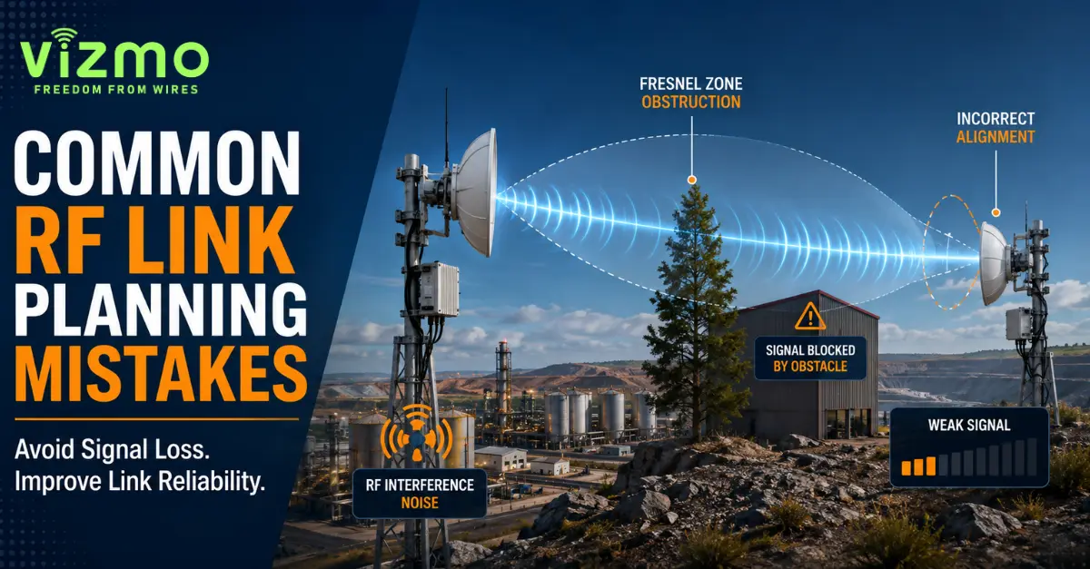
2. Assuming Visual Line of Sight Is Enough
Being able to see one antenna from another does not automatically guarantee a strong wireless link.
Radio waves occupy an area around the direct signal path. An important part of this area is called the Fresnel zone.
Trees, buildings, terrain, machinery, or other structures entering this zone can weaken the signal even when the two antennas are visually visible to each other.
Common Mistake
An installer checks the locations visually and assumes that because the remote antenna can be seen, the wireless link will perform correctly.
The connection may still experience reduced signal quality or unstable performance.
Better Approach
Check both:
- Direct line of sight
- Fresnel zone clearance
For longer point-to-point wireless links, antenna height can become just as important as antenna gain. Increasing antenna height may sometimes provide a better result than simply increasing transmit power.
3. Choosing the Wrong Frequency for the Application
Not every wireless frequency behaves in the same way.
Higher frequencies can provide useful bandwidth and support high-capacity connections, but propagation, obstacle penetration, antenna requirements, available spectrum, and interference conditions vary between bands.
Lower-frequency systems can be useful when long-range communication or stronger propagation characteristics are important.
For example, sub-GHz technologies may be considered for remote industrial connectivity where coverage is more important than very high throughput.
Vizmonet explains this in more detail in its guide on why sub-1 GHz Wi-Fi HaLow is important.
For Wi-Fi HaLow deployments, engineers should also consider network topology, coverage, interference, and device placement as part of industrial Wi-Fi HaLow network design.
Wi-Fi systems are based on the IEEE 802.11 family of standards. Engineers who need standards-level information can refer to the official IEEE 802.11 wireless LAN standard.
Meanwhile, 2.4 GHz, 5 GHz, 6 GHz, and other frequency ranges may be selected depending on capacity, device support, antenna size, spectrum availability, and application requirements.
Better Approach
Choose the operating frequency based on:
- Required range
- Required throughput
- Local spectrum regulations
- Interference environment
- Available channel bandwidth
- Antenna requirements
- Terrain
- Obstacles
- Device compatibility
- Application requirements
4. Selecting an Antenna Only by Gain
Antenna gain is important, but higher gain does not automatically mean better wireless performance.
Different antennas distribute RF energy in different ways.
Omnidirectional Antennas
Omnidirectional antennas transmit and receive signals across a wide horizontal area. They can be useful when devices are located in several directions around a central access point.
Directional Antennas
Directional antennas concentrate RF energy towards a specific direction.
They are commonly used for:
- Point-to-point wireless links
- Wireless backhaul
- Long-distance connections
- Connections between fixed locations
For a detailed explanation of antenna gain, radiation pattern, installation requirements, and other factors, read Vizmonet’s industrial wireless antenna selection guide.
Common Mistake
Choosing the antenna with the highest dBi value without considering radiation pattern, beamwidth, mounting location, orientation, or network topology.
Better Approach
Evaluate:
- Antenna type
- Gain
- Beamwidth
- Polarisation
- Frequency support
- Installation height
- Mounting conditions
- Cable length
- Required coverage area
5. Ignoring Cable and Connector Losses
RF energy is lost as it travels through cables and connectors.
Long cable runs between the radio and antenna can significantly affect the link budget. Every connector, adapter, splitter, or damaged cable can introduce additional losses.
Better Approach
- Keep RF cable runs as short as practical
- Use suitable low-loss RF cable
- Reduce unnecessary adapters
- Use properly rated connectors
- Protect outdoor connections from moisture
- Inspect connectors during maintenance
6. Ignoring Receiver Sensitivity
Transmit power receives significant attention during wireless link planning, but the receiving side is equally important.
Receiver sensitivity indicates how weak a signal the radio can detect at a particular data rate or modulation.
A received signal slightly above the minimum sensitivity level may establish communication, but that does not necessarily mean the link has enough reliability for an industrial application.
Better Approach
Compare calculated received signal strength with the receiver sensitivity required for the intended operating mode.
The difference contributes to the available link margin. Avoid designing critical wireless links to operate continuously at the edge of receiver sensitivity.
7. Designing With Too Little Link Margin
Wireless conditions are rarely constant. Signal levels can change because of:
- Rain
- Vegetation
- Vehicles
- Moving machinery
- New buildings
- Temporary equipment
- Antenna movement
- Cable ageing
- RF interference
- Atmospheric conditions
What Is Link Margin?
Link margin is the difference between the expected received signal level and the minimum signal level required by the receiver.
A stronger margin gives the network more tolerance to unexpected losses.
Better Approach
Do not plan only for perfect conditions. Include reasonable engineering margin based on the importance of the link, distance, frequency, environment, equipment, and availability requirements.
8. Underestimating RF Interference
Strong signal strength does not always mean good wireless performance.
Another transmitter operating on or near the same frequency can affect communication. Industrial environments may contain multiple RF and electrical systems.
These can include:
- Wi-Fi networks
- Wireless sensors
- Two-way radios
- Telemetry systems
- Bluetooth devices
- Video links
- Industrial equipment
- High-power electrical systems
Better Approach
- Perform a spectrum assessment where practical.
- Identify existing wireless systems.
- Check channel utilisation.
- Review nearby RF transmitters.
- Select channels carefully.
- Maintain suitable antenna separation where required.
A reliable wireless link requires both sufficient signal strength and acceptable signal quality.
9. Treating Manufacturer Maximum Range as Guaranteed Range
A wireless product may be capable of communicating over a long distance under suitable conditions. However, maximum range figures should not replace proper RF link planning.
Real-world performance depends on:
- Antenna configuration
- Frequency
- Channel width
- Modulation
- Transmit power
- Receiver sensitivity
- Terrain
- Interference
- Obstacles
- Regulatory limits
Topology also affects the design. Engineers deciding between different network structures can review point-to-point wireless vs mesh networks to understand the key differences.
10. Ignoring Antenna Height and Alignment
A correctly selected antenna can still perform poorly if it is installed incorrectly.
Directional antennas require accurate alignment. Even a small change in direction can reduce received signal strength when the antenna has a narrow beam.
Antenna height also affects:
- Line of sight
- Fresnel zone clearance
- Obstacle avoidance
- Coverage pattern
Better Approach
- Confirm antenna orientation
- Check polarisation
- Measure signal strength during alignment
- Secure mounting hardware
- Consider wind loading
- Verify mounting height
- Record final antenna positions
11. Ignoring the Physical Environment
RF planning performed only from maps or software cannot always show everything happening at an industrial site.
Possible challenges include:
- Large metal structures
- Storage tanks
- Cranes
- Heavy vehicles
- Moving equipment
- Dense vegetation
- Temporary buildings
- Stockpiles
- Terrain changes
Metal surfaces can also create signal reflections and multipath conditions.
Better Approach
Combine RF planning tools with real site knowledge. Consider the following questions:
- What obstacles exist today?
- Could new equipment appear later?
- Are vehicles regularly moving through the RF path?
- Will vegetation grow?
- Could antenna mounts move because of wind or vibration?
- Are there large reflective surfaces nearby?
12. Skipping the RF Site Survey
Planning software and RF propagation models are useful tools, but they are based on assumptions and available data.
A practical RF site survey can include:
- Location coordinates
- Distance measurements
- Antenna mounting options
- Existing wireless activity
- Potential obstructions
- Cable routing
- Power availability
- Environmental conditions
- Spectrum observations
- Signal measurements
For remote industrial sites, collecting this information before installation can prevent expensive changes later.
13. Forgetting Regulatory Requirements
RF systems must operate within the regulations that apply in the country or market where the equipment is deployed.
Regulatory requirements may affect:
- Permitted frequencies
- Maximum transmit power
- Effective radiated power
- Channel use
- Equipment certification
- Antenna configuration
Vizmonet provides further information about wireless product certification, testing, and compliance for OEMs developing wireless products.
For products targeting multiple markets, see Vizmonet’s global regulatory compliance and homologation services.
In the United States, RF devices may need to meet specific equipment-authorisation requirements before marketing or import. Engineers and OEMs can refer to the official FCC Equipment Authorization guidance for regulatory information.
For international spectrum planning, the ITU Radio Regulations provide the international regulatory framework governing the use of the radio-frequency spectrum and satellite orbits.
Regulatory compliance should therefore be considered during RF planning and product selection rather than being checked only at the final deployment stage.
14. Focusing Only on Signal Strength
Signal strength is important, but it is only one part of wireless performance.
A network can show a strong signal and still have poor throughput because of:
- High noise
- Interference
- Retransmissions
- Poor signal-to-noise ratio
- Congested channels
- Incorrect channel width
- Multipath conditions
Better Approach
Depending on the radio platform, monitor:
- RSSI
- Signal-to-noise ratio
- Noise floor
- Data rate
- Packet loss
- Latency
- Retransmissions
- Actual throughput
Vizmonet’s guide to radio performance metrics provides additional context on the parameters used to evaluate wireless performance.
The goal of RF link planning is not simply to establish a connection. The link must support the actual performance requirements of the application.
15. Not Testing the Wireless Link After Installation
An RF link budget predicts performance. Field testing confirms it.
After installation, verify:
- Received signal level
- Noise level
- Link stability
- Packet loss
- Throughput
- Latency
- Antenna alignment
- Performance during normal site activity
For critical applications, testing should represent realistic operating conditions rather than only a short test immediately after installation.
A Practical RF Link Planning Process
Step 1: Define the Application
Determine:
- Required distance
- Throughput
- Latency
- Availability
- Number of devices
- Mobility requirements
Step 2: Study the Site
Review terrain, buildings, equipment, vegetation, and possible antenna locations.
Step 3: Select the Frequency
Choose a frequency range suitable for coverage, capacity, environment, equipment, and local regulations.
Step 4: Check the RF Path
Evaluate both line of sight and Fresnel zone clearance.
Step 5: Select the Antennas
Choose the antenna type, gain, beamwidth, and mounting configuration based on the network topology.
Step 6: Calculate the RF Link Budget
Include transmit power, antenna gain, path loss, receiver sensitivity, cable losses, and other expected losses.
Step 7: Check Interference
Review the RF environment and identify competing transmitters or noisy channels.
Step 8: Add Suitable Link Margin
Allow for real-world changes and unexpected signal losses.
Step 9: Install Carefully
Correctly position, align, mount, seal, and secure the RF equipment.
Step 10: Validate the Network
Measure actual wireless performance and compare it with the design expectations.
Application Requirements → Site Analysis → Frequency Selection → RF Path → Link Budget → Antenna Selection → Interference Analysis → Link Margin → Installation → Field Validation
RF Link Planning Checklist
| Planning Area | Question to Check |
|---|---|
| Application | What data and performance does the wireless link need? |
| Distance | How far apart are the radios? |
| Frequency | Is the selected frequency band suitable for the environment? |
| Regulations | Is the RF configuration permitted in the deployment region? |
| Line of Sight | Is the direct RF path clear? |
| Fresnel Zone | Are obstacles affecting the Fresnel zone? |
| Antenna | Is the antenna type and gain suitable? |
| RF Cable | Have cable and connector losses been included? |
| Link Budget | Is the expected received signal power sufficient? |
| Receiver | Has receiver sensitivity been considered? |
| Link Margin | Is there enough tolerance for changing conditions? |
| Interference | Has the local RF environment been reviewed? |
| Installation | Are antenna height, alignment, and mounting correct? |
| Testing | Has actual field performance been verified? |
How Better RF Link Planning Improves RF Networking
Good RF networking is built from reliable individual wireless links.
When each link is properly planned, organisations can achieve:
- More stable wireless connectivity
- Better coverage
- Fewer unexpected outages
- More predictable throughput
- Reduced troubleshooting
- Easier network expansion
- Better use of available RF spectrum
- Lower risk of expensive installation changes
This becomes increasingly important as industrial sites connect more sensors, machines, cameras, mobile systems, autonomous equipment, and remote assets.
RF Link Planning for Industrial Applications
Mining
Mining operations may require communication across large outdoor areas, uneven terrain, pits, moving machinery, and remote operational zones.
Learn more about the requirements and challenges of wireless connectivity for smart mining operations.
Oil and Gas
Oil and gas facilities may need to connect widely separated equipment while operating in demanding outdoor environments.
Vizmonet explains these requirements in its guide to industrial wireless networks for oil and gas operations.
Agriculture
Remote sensors, cameras, machinery, irrigation systems, and field equipment may require connectivity across large areas where wired infrastructure is difficult to install.
Heavy Construction
Construction site layouts can change regularly as equipment, materials, temporary buildings, and vehicles move.
Industrial IoT
Large numbers of connected devices may require predictable communication while sharing available spectrum with other wireless systems.
Remote Monitoring
Remote monitoring systems often depend on stable links to move sensor, telemetry, video, or equipment data from difficult-to-access locations.
See how industrial wireless connectivity supports remote monitoring systems.
UAV and UGV Applications
Unmanned aerial and ground systems introduce mobility, changing link distance, antenna orientation, and dynamic RF paths.
For UAV applications, read more about long-range drone connectivity solutions.
RF Link Planning for Wireless Backhaul Networks
RF planning becomes especially important when wireless links are used to carry data between remote sites or network segments.
A backhaul link may support cameras, industrial IoT systems, control networks, telemetry, or remote operations. Failure of one backhaul connection can therefore affect several downstream systems.
For additional guidance, see Vizmonet’s article on wireless backhaul networks for industrial connectivity.
Build the Wireless Link Around the Application
A reliable wireless network should start with application requirements, not only with a radio specification.
Before selecting hardware, define:
- What needs to connect?
- How far does the wireless signal need to travel?
- How much data must the link carry?
- What obstacles are present?
- How reliable must the connection be?
- What RF conditions exist at the site?
The answers help determine the appropriate radio, antenna, frequency, network architecture, and installation method.
The objective is not always to use maximum transmit power or maximum antenna gain. The objective is to design the right RF system for the application.
Plan Reliable Industrial Wireless Connectivity With Vizmonet
Industrial wireless networks often operate in environments where range, interference, temperature, vibration, obstacles, and changing site conditions must all be considered together.
Vizmonet provides wireless engineering and product development services for demanding industrial and embedded wireless applications.
If you are planning an industrial wireless system, point-to-point connection, remote monitoring network, wireless backhaul, or specialised RF application, selecting the right radio technology is only one part of building a reliable network.
Start with the RF link. Design for the environment. Validate before deployment.
Try the Vizmonet RF Link Planner to evaluate your wireless link requirements before deployment.
For application-specific engineering support, contact Vizmonet to discuss your RF requirements with the team.
Conclusion
Successful RF link planning is not based on a single specification.
Transmit power, antenna gain, path loss, receiver sensitivity, Fresnel zone clearance, RF interference, cable losses, frequency selection, environmental conditions, and regulatory requirements all influence wireless performance.
The most common RF planning problems usually begin when one or more of these factors are ignored.
Plan the Path → Calculate the Link → Check the RF Environment → Install Correctly → Measure the Result
Following this process can help create industrial wireless networks that are more predictable, scalable, and reliable over the long term.
For organisations deploying wireless connectivity across remote or demanding industrial environments, careful RF planning at the beginning can prevent much more difficult network problems after installation.